



Overview of OTC Welding Robot External Safety Circuits and Interface Terminal Blocks
In the system integration and on-site debugging of industrial automated arc welding workstations, the electrical interlock safety communication between the robot control cabinet and external peripheral equipment (such as safety light curtains, tooling fixture positioners, safety door locks, bus PLCs, or main consoles) is the lifeline for ensuring safe production. OTC DAIHEN arc welding robot control cabinets (such as the standard FD11, FD19, etc.) specifically integrate two core external signal interface terminal blocks inside the control box, namely TBEX1 and TBEX2.
These two terminal blocks are primarily responsible for carrying the robot’s dual-channel safety circuit input (such as external emergency stop, teaching enable action switch, safety plug interlock) and hardware-level status signal output (such as dry contact emergency stop output, CPU exception output). Correctly understanding and standardizing the connection of TBEX1 and TBEX2 can effectively prevent control cabinet hardware burnout or safety refusal failures caused by insulation breakdown or logic errors. Below, we provide an in-depth breakdown of each pin number, signal name, and specific electrical connection method for these two terminal blocks.
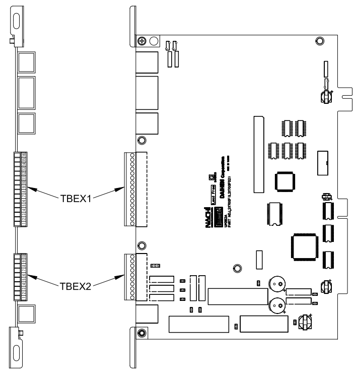
Opening the OTC welding robot control cabinet, we can see two terminal blocks, TBEX1 and TBEX2. Their exact locations and corresponding layout are shown below:
Before wiring and debugging, we first need to refer to the comparison chart below to correctly identify the signal pin numbers and corresponding physical locations of the TBEX1 and TBEX2 terminal blocks:
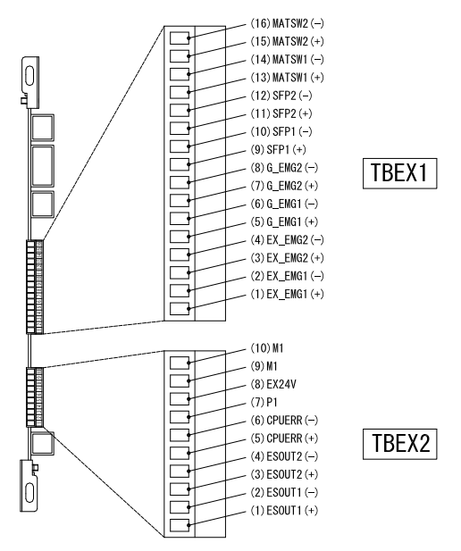
1. TBEX1 Terminal Block: Core Dual-Channel Safety Input Definition Table
The TBEX1 terminal block is mainly used to connect various external hardware-level safety protection input signals. The OTC control cabinet adopts strict dual-circuit (dual-system redundancy) hard-wired self-locking logic internally, where each safety signal consists of two independent channels: positive (+) and negative (-). At the factory, some terminals that do not require external interlocking are fitted with physical jumper wires by default. When substituting with external signals, the original jumper wires must be removed in pairs; never short-circuit a single loop.
| Pin No. | Signal Name | Standard Content (Function) | Electrical Wiring & Technical Notes |
|---|---|---|---|
| 16 | MATSW2 | Teach Enable Switch Input 2- | Static Teach Enable (Safety Enable Switch) External Input: Used to connect the safety enable switch of the externally attached handheld console. The original factory setting is that physical short-circuit jumper wires are installed between 13-14 and 15-16. If an external circuit needs to be introduced, the original jumper wires must be removed in pairs, and the normally closed (NC) dual contacts of the external device must be connected. |
| 15 | Teach Enable Switch Input 2+ | ||
| 14 | MATSW1 | Teach Enable Switch Input 1- | |
| 13 | Teach Enable Switch Input 1+ | ||
| 12 | SFP2 | Safety Plug Input 2- | Safety Plug / Safety Door Lock Circuit Terminal: Specifically used to connect the perimeter safety door switch, safety light curtain, or safety mat of the arc welding workstation. This signal belongs to the hardware control chain and must remain in a closed conducting state for the robot to start. Once the external perimeter door is opened and the contact is disconnected, the robot system will instantly cut off servo power. |
| 11 | Safety Plug Input 2+ | ||
| 10 | SFP1 | Safety Plug Input 1- | |
| 9 | Safety Plug Input 1+ | ||
| 8 | G-EMG2 | G-STOP Input 2- | G-STOP (External Stop / Controlled Protective Stop) Signal Terminal: This terminal is used for external automatic control systems (such as the main control PLC or tooling jigs) to trigger a program pause or controlled protective stop of the robot. The factory setting is that jumper short-circuit lines are installed between 5-6 and 7-8. These short-circuit lines need to be removed when connecting to the external field safety bus. |
| 7 | G-STOP Input 2+ | ||
| 6 | G-EMG1 | G-STOP Input 1- | |
| 5 | G-STOP Input 1+ | ||
| 4 | EX-EMG2 | External Emergency Stop Input 2- | External Emergency Stop (EX-EMG) Dual-Channel Input Terminal: Used to introduce the main control emergency stop button of the entire automated assembly line, or the emergency stop hard signal of the positioner machine table. The default setting from the factory is that short-circuit jumper wires are installed between 1-2 and 3-4. During on-site integration, the jumper wires must be removed in pairs, and external dual-circuit self-locking emergency stop normally closed contacts meeting the safety level must be connected. |
| 3 | External Emergency Stop Input 2+ | ||
| 2 | EX-EMG1 | External Emergency Stop Input 1- | |
| 1 | External Emergency Stop Input 1+ |
2. TBEX2 Terminal Block: External Power Switching and Hardware Status Output Table
The TBEX2 terminal block is primarily responsible for the switching between the switching power supply inside the robot control cabinet and the external DC low-voltage power supply (DC24V), as well as providing hardware-level dry contact (voltage-free contact) status feedback to peripheral integrated systems. Through this terminal block, it can be realized that when the main power of the control cabinet is cut off, the external safety interlock system can still monitor the status of the current emergency stop button.
| Pin No. | Signal Name | Standard Content (Function) | Electrical Wiring & Technical Notes |
|---|---|---|---|
| 10 | Ml | External Power Ground (GND) | External DC Power Supply Ground and 24V Input Terminal: By externally connecting an external regulated power supply (DC24V) between the EX24V and M1 terminals, the operation emergency stop circuit can be ensured even when the main power supply of the control device is completely cut off. At this time, the external system can still close/disconnect ESOUT1 and ESOUT2 through the emergency stop state. Note: It must be used in conjunction with the JP1 jumper pins in the cabinet to switch jumpers between the internal power supply (factory setting) and the external power supply. |
| 9 | |||
| 8 | EX24V | External Power 24V Input | |
| 7 | P1 | Internal DC24V Power Positive | Robot Internal Dedicated Power Terminal: This is the DC24V power output terminal inside the robot control unit. Since this power is dedicated to internal control microcircuits, it is strictly prohibited to output this power to drive external strong-current equipment (such as external valve bodies or high-power relays). Do not misuse this terminal when installing non-standard small components inside the cabinet to prevent transient surges from reverse-breaking the circuit board. |
| 6 | CPUERR | CPU Error Output – (Dry Contact) | CPU System Action Status Error Output Feedback: A normally open (NO) contact (passive dry contact) output terminal representing the action status of the main control core. When the CPU inside the control device experiences a communication breakdown, crash, fatal hardware damage, or a complete collapse of internal logic, this passive contact closes (ON), and the external relay system can instantly grab the exception to perform whole-line shutdown protection. |
| 5 | CPU Error Output + (Dry Contact) | ||
| 4 | ESOUT2 | Emergency Stop Output 2- (Dry Contact) | Emergency Stop Status Dual Redundant Feedback Output (Dry Contact): A normally open (NO) contact (passive dry contact) output used to indicate the current robot emergency stop status. When the red emergency stop button on the control cabinet operation panel or the suspended teach pendant (TP) is pressed, this signal is disconnected (OFF/contact becomes open). This output consists of 2 completely independent system hardware-level dry contacts, ensuring a high standard of dual redundant safety, and is commonly used to cut off the primary power supply of an external welding machine. |
| 3 | Emergency Stop Output 2+ (Dry Contact) | ||
| 2 | ESOUT1 | Emergency Stop Output 1- (Dry Contact) | |
| 1 | Emergency Stop Output 1+ (Dry Contact) |
Quickly Obtain Control Cabinet Core Components and Technical Support
Improper on-site wiring, external high voltage intrusion, or high-frequency arc discharge can easily cause the TBEX external terminal block of the control cabinet to scorch, internal safety relays to be damaged, or the main control CPU interface board to burn out. You are welcome to provide the specific accessory codes you need (such as relays, power units, filter boards, motherboards) and contact us directly to obtain the latest official standard quotes, spot inventory, or get more detailed system integration wiring reference drawings:
Why Stick to Official Original OTC DAIHEN Accessories in Safety Circuit Integration?
The emergency stop and interlock circuit of the industrial welding robot belongs to a hardware chain with an extremely high safety level, which is directly related to the life safety of workshop operators and the asset protection of expensive electromechanical equipment on the whole line. Adopting non-original refurbished safety boards or non-original relays can easily cause the system to refuse emergency stop in the event of a collision or personnel intrusion due to delayed pull-in, contact adhesion, or insufficient resistance to high-frequency noise crosstalk. At the same time, if external high voltage back-feeds and breaks down the terminal block due to leakage, the lack of original absorption circuit protection can easily cause the main CPU of the entire control cabinet to be completely scrapped. We promise that all control cabinet terminal blocks, safety relay units, logic switching power supplies, and complete sets of multi-axis body cables we supply are 100% Brand New Official Original Genuine Products. If you need to confirm today’s spot inventory of spare parts, request a fault code clearing guide, or need technical consultation on Fronius special high-precision system accessories, please feel free to consult our technical service team at any time.