



OTC Daihen Welding Robot Encoder Calibration Technical Background in Non-Origin Status
In industrial on-site maintenance, we often encounter situations where the robot loses absolute value encoder data due to various unexpected events (such as battery depletion or signal interruption). The ideal reset state is when the mechanical arm exactly stops at the standard “mechanical origin” (i.e., the position after executing the 9999 origin program).
However, in actual production, robots often suddenly report encoder abnormalities in non-origin positions (such as mid-trajectory, inside a deep cavity, or after a collision stoppage). At this point, since the system has lost its ability to track the current spatial coordinates, traditional origin reset methods will become completely invalid. Blindly executing a routine reset in the wrong posture will cause a catastrophic overall physical deviation of all trajectories in the original robot program.
This article provides you with a rigorous two-stage illustrated operation guide for encoder calibration in a non-origin status. Equipment maintenance personnel are requested to strictly follow the steps below on the teach pendant for progressive recovery:
1. Phase One: Enter Advanced Specialist Mode and Software Reset of Encoder
Because encoder calibration involves overwriting underlying control constants and is a high-risk operation, the system’s security protection level must first be breached. Please follow the illustrated steps below to click on the operation box or teach pendant:
Enter Control System Boot Main Interface
Confirm the control cabinet power is normally turned on, wait for the teach pendant to fully load the system, and enter the conventional boot monitoring or manual operation main interface.
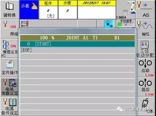
Step-01: Teach pendant system load ready interface
Press the [R] Reset Key on the Keyboard
In the physical button area of the teach pendant, press the reset key marked with [R] to call up the hidden system command input dialog.
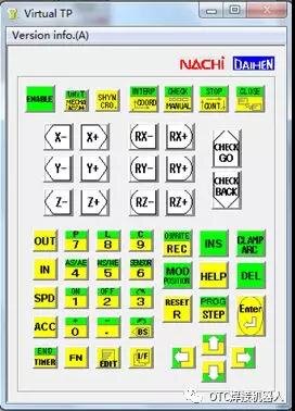
Step-02: Press the R button to activate special command input
Enter the Hidden Code [314] via Numeric Keys
In the pop-up command input box, sequentially and precisely enter the OTC official underlying security unlock code via the teach pendant keyboard: 314.
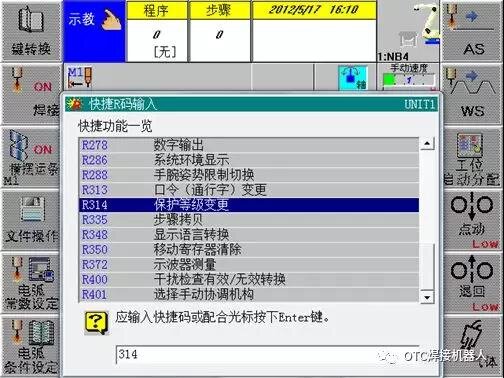
Step-03: Enter the special unlock code 314
Press the Physical [Enter] Key to Submit Change
After verifying the entered numbers are correct, press the [Enter] confirmation key at the bottom right of the teach pendant, and the system will jump to the protection level change special input window.
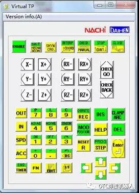
Step-04: Press the Enter key to submit the level change request
Enter Specialist Level Security Password [12345]
In the immediately popping up Password input box, type the OTC specialist pass code: 12345, and then press the confirmation key again.
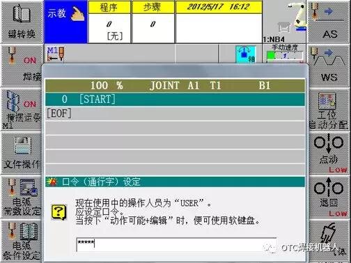
Step-05: Type the specialist pass code 12345
Confirm Security Level Successfully Switched to [SPECIALIST]
At this time, the screen will show that the protection level has been successfully changed to the highest privilege level SPECIALIST. Click anywhere on the screen or press any key to return to the main menu.
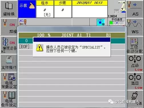
Step-06: The system is now in SPECIALIST privilege mode
Combination Key [Enable + F5] to Enter Constant Setting
Use your left hand to tightly hold down the [Enable] safety switch on the back or front of the teach pendant, and synchronously press the [F5 Constant Setting] shortcut key with your right hand to forcefully wake up the underlying setting menu.
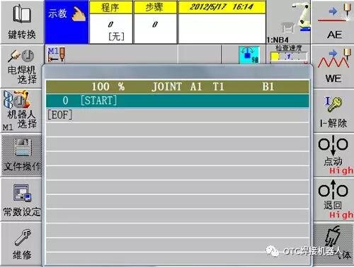
Step-07: Enter the fully digital constant setting tree menu
Move Cursor Down to 3rd Item [Mechanical Constant] and Confirm
Use the arrow keys to move the highlighted cursor down to the third main menu item—[Mechanical Constant], and press the Enter key to enter the sub-directory.
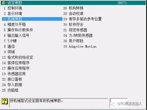
Step-08: Select and enter the underlying control item of mechanical constant
Continue Down to 4th Item [Encoder Calibration] and Confirm
Within the mechanical constant sub-menu, precisely stop the cursor at the fourth sub-item—[Encoder Calibration], and press Enter to enter the core calibration parameter matrix interface.
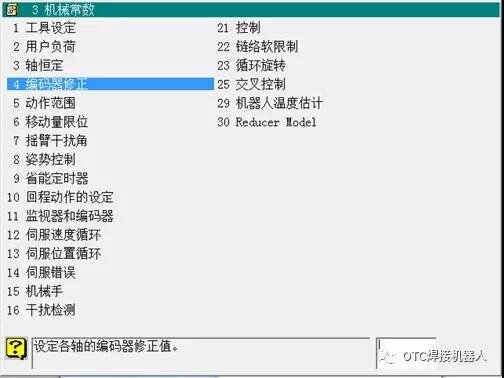
Step-09: Enter the encoder pulse calibration parameter modification page
Press the [F9 Encoder Reset] Function Button at the Bottom
After entering the interface (at this time the data displayed are all residual erroneous values under the original non-origin status), directly press the shortcut function key at the bottom of the teach pendant—[F9 Encoder Reset].
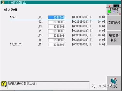
Step-10: Execute the F9 command to initiate the encoder reset process
Press [F7 Select All] to Cover All Robot Axes
To ensure the reconstruction of the robot’s overall coordinate system, directly press [F7 Select All] under this interface to place all joint axes from J1 to J6 in a highlighted checked reset state.
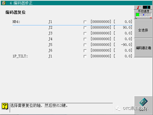
Step-11: Select all joint axes from J1 to J6
Press [F12 Execute] and Confirm, Power Off to Completely Restart
Press [F12 Execute] and check to confirm. **Note: If the system pops up a “Please turn off operation preparation” prompt, please immediately press the large mushroom emergency stop switch on the operation box**. After completing the software reset, you must completely turn off the main power of the control cabinet, wait for 10 seconds, and turn it on again so that the control motherboard can thoroughly refresh the zero position registers.
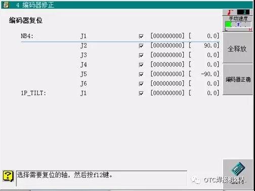
Step-12: Execute F12 to complete the clearing action at the software level
2. Phase Two: Absolute Alignment of Mechanical Scales for Each Axis and Writing Spatial Position Records
After completing the software level refresh, since the system is currently in an arbitrary physical posture at the non-origin, we need to manually pull the robot back to the physical origin, and conduct the “ultimate binding” of physical and digital coordinates:
Manually Move Single-Axis Coordinates, Strictly Align the Physical Red Triangle Scale of Each Axis
After restarting, switch the operation mode to manual low-speed status. Switch to [Axis Coordinate] movement mode, **extremely patiently rotate each axis of J1, J2, J3, J4, J5, J6 one by one, until the physical red triangles on the skeleton of each axis align perfectly in an absolute straight line with the scale lines (scale points)**. This is the crucial physical step determining that the subsequent trajectory precision will not drift!
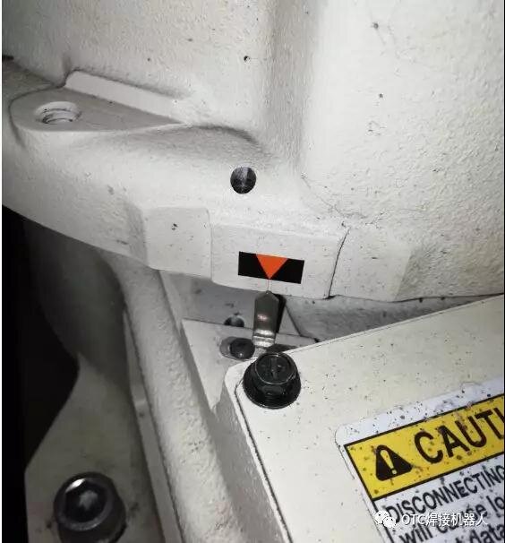
Step-13: Precise manual fine-tuning with the naked eye to align the skeleton scale of each axis
Repeat Previous Steps Again to Re-enter the [Encoder Calibration] Parameter Page
Keep the mechanical arm aligned with the physical zero position absolutely static. Utilize the combination path [Enable + F5] -> [Mechanical Constant] -> [Encoder Calibration] again to re-enter the calibration data page for a second time.
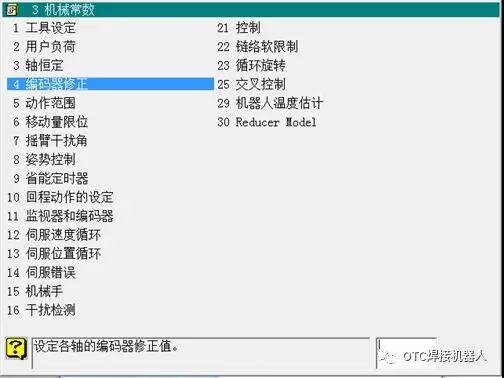
Step-14: Keep the physical origin static, enter the constant page again
Select [Position Record] and Execute [Write] to Reconstruct the Lifeline
On the interface, move the cursor to the [Position Record] function item, press confirm and execute the [Write] command. Similarly, if the system throws an operation preparation disconnect prompt, press the emergency stop mushroom head. After the writing is completed, **finally perform a whole-system power off and complete boot restart**. By this point, the spatial position information of the robot’s original machining program will have completely achieved lossless reset, and the system is reborn!
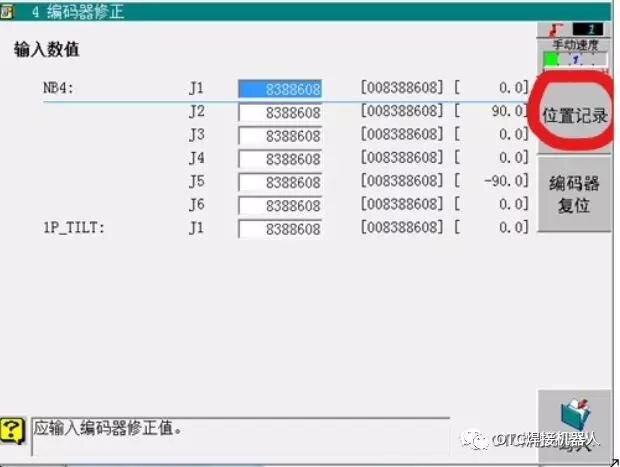
Step-15: Write physical coordinate data to thoroughly activate the original welding program
Industrial On-Site Non-Origin Status Overhaul and Encoder Recovery Error Prevention Red Card Warning:
- Blindly Executing “Position Record Write” Before Physical Scales Are Aligned is Strictly Prohibited: The write action in Step 15 is telling the system “the current posture is the physical 0-degree origin”. If you handle Step 13 perfunctorily and forcefully click “write” while the mechanical arm is in a skewed posture without aligning the red triangles, the control cabinet will solidify this deformed posture as the new origin. Afterwards, once you run your original high-precision welding trajectory program, the robot will experience violent physical rollovers due to spatial logic disorder, or even hit the surrounding safety fences and tooling locating pins at full speed, causing the electromechanical system to be completely scrapped!
- Prevent the Fatal Chain Reaction of Powering Off to Unplug the Battery: The reason why such complex non-origin calibration occurs is often because maintenance personnel violate the mandatory rule of “battery must be replaced while powered on” when replacing the robot’s backup lithium battery (control cabinet motherboard battery or main body axis battery), and unplug the battery in a power-off state, causing the multi-axis absolute value encoder memory to instantly clear to zero. It is strictly warned here: **Whenever replacing the encoder backup battery in the future, the robot control cabinet must be kept in an energized and lit state**. Cut the zip ties and execute a quick replacement to completely avoid such non-origin overhauls.
️ Obtain OTC Official Encoder Holding Batteries, Core Boards & Original Expert Technical Support
The calibration of absolute value encoders and the reconstruction of mechanical zero points are extremely difficult underlying electromechanical technologies in industrial robot integration and commissioning. If your workshop team encounters stubborn errors during the execution of non-origin calibration, position record writing, or live replacement of lithium batteries, do not operate blindly by force. Welcome to directly dial our expert technical hotline, and we will provide you with standard accurate original backup batteries, direct supply of main control boards, and the most professional remote/on-site software and hardware technical support: