



Core Value of OTC Daihen Robot Relay Devices and External General I/O Expansion
In the integrated design of modern automated arc welding stations, the robot control cabinet not only needs internal communication with the digital welding power source but also requires frequent interlocking and communication of switching signals with automated peripheral equipment around the workstation (such as pneumatic solenoid valves for tooling fixtures, sliding rail servo axes, safety light curtains, safety door locks, and the main control PLC system for the entire line). As control systems become more precise, the factory-installed input/output points of the robot control cabinet often face shortages.
To resolve the limitations of insufficient points, OTC DAIHEN has designed dedicated Relay Devices and General I/O Expansion Boards for FD series and other robots. By cascading through the dedicated internal bus of the control cabinet (supporting the connection of up to 2 relay devices and 2 I/O expansion boards), enterprises can exponentially expand the hardware switching resources of the control system. Correct and standardized installation of the relay device can effectively establish a high-protection electrical barrier, preventing major equipment hidden dangers such as wire feed slipping, signal packet loss, and baseboard breakdown caused by excessive external wiring impedance or insulation aging.
I. Detail Configuration of General I/O Points Expandable via OTC Robot System Cascading
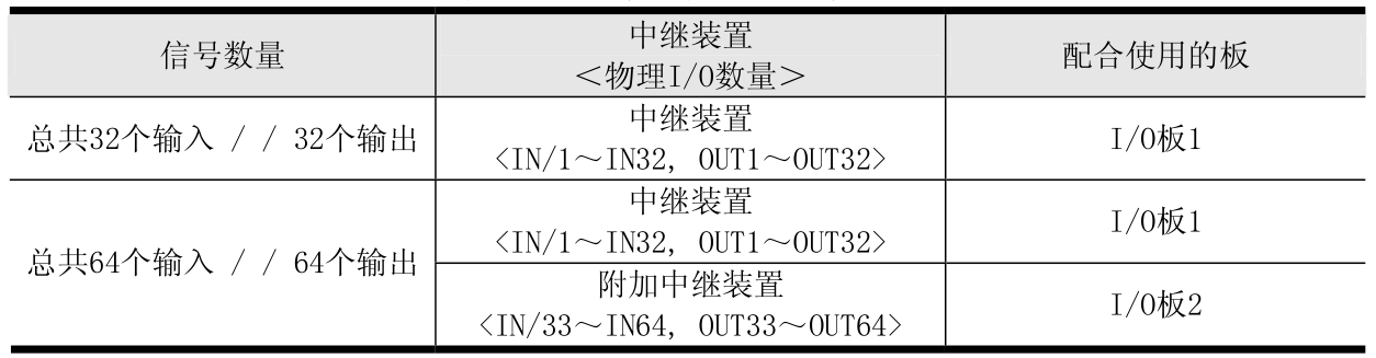
To provide precise data references for your on-site integration designers, the following table details the total scale of points the control system can achieve after adding different numbers of relay devices and I/O boards (the table adopts a deepened solid line design, rigorously and clearly arranged):
| Hardware Configuration Combination (Configuration) | Expanded Input Points (Inputs) | Expanded Output Points (Outputs) | Cascaded Bus Function and Interlock Application Scope Description |
|---|---|---|---|
| Standard Basic Configuration (Only comes with the robot control cabinet) |
Standard Built-in Input Points | Standard Built-in Output Points | Only satisfies the most basic single-station, single-torch arc ignition, arc end, and workstation emergency stop interlocks. |
| Using 1 Relay Device (Adding 1 standard I/O expansion board) |
+ 32 Points (After addition) | + 32 Points (After addition) | Satisfies status feedback of standard dual-station positioners, pneumatic fixtures, and torch cleaner linkage. |
| Using 2 Relay Devices (Cascading 2 standard I/O expansion boards) |
+ 64 Points (Maximum limit) | + 64 Points (Maximum limit) | Applicable to complex multi-station assembly lines for auto parts, and remote group control by main consoles. |
Figure 1: OTC Daihen Official Factory Chart on the Quantity Relationship of External I/O Points Expandable by Relay Devices
II. Physical Installation Location Diagram for Relay Devices, Terminal Blocks, and Expansion I/O Boards
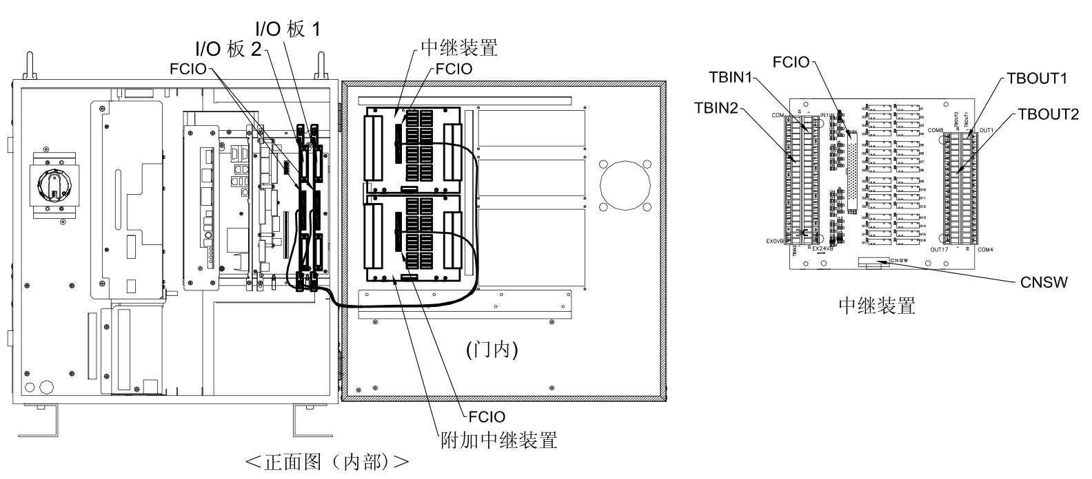
Before executing hardware threaded fixing, please first verify the physical placement positions of the following official standard cabinet internal card slots and baseplate space based on your hardware addition quantity (1 set or 2 sets cascaded):
Figure 2: Official Designated Installation Slots When Adding [1 Relay Device, Terminal Block, and I/O Expansion Board] Inside the Control Cabinet
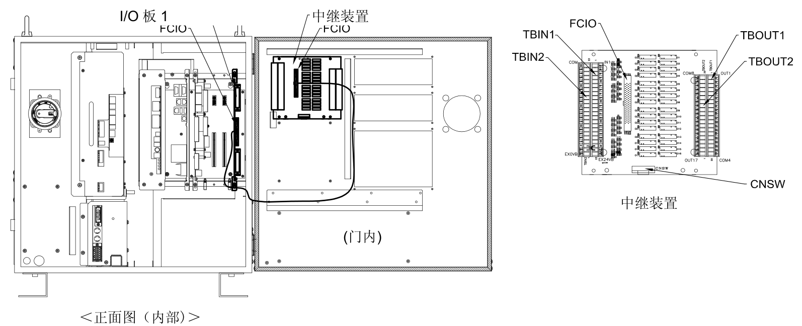
Figure 3: Spatial Stacking and Screw Hole Position Diagram When Cascading [2 Relay Devices, Terminal Blocks, and Additional I/O Boards] Inside the Control Cabinet
Special Ordering and Maintenance Note: If you ordered custom multi-station linkage tooling or multi-axis external positioners as a complete set when initially purchasing the OTC welding robot system, the aforementioned relay devices and I/O expansion boards are usually pre-installed and fixed on specific rails or sheet metal baseplates inside the control cabinet at the factory. If these are spare parts purchased separately by you later to upgrade the assembly line, modify processes, or install non-standard tooling on your own, physical installation must be strictly executed according to the industrial-grade maintenance steps below.
III. Five-Step Tutorial for Hardware Quick Replacement and Shockproof Wiring of Expansion Relay Components
Before adding hardware in the interface area between strong and weak power inside the control cabinet, you must ensure that the entire electrical environment is in an absolutely disconnected and safe state:
Cut Off Main Distribution Grid Power, Disconnect Circuit Breakers, and Wait for Discharge
⚠️ Electrical Shock Prevention Safety High-Risk Interlock Standard: Before starting, you must thoroughly pull the switch to disconnect the feed circuit breaker of the main distribution grid. Close the main air circuit breaker switch on the front panel of the robot control cabinet. Because the DC main bus energy storage capacitors inside the control cabinet inverter room contain residual charges up to several hundred volts, you must force a wait time of at least 5 minutes or more. Only after confirming that the residual capacitor power has been safely discharged can you open the cabinet to operate. Maintenance personnel must wear anti-static ESD wristbands to prevent static shocks from damaging the integrated microelectronic components on the board.
Remove Control Device External Structure Panels and Establish a Clean Maintenance Surface
Use a Phillips screwdriver to remove the sheet metal dust-proof protection panel on the right side or rear back of the robot control cabinet, and centralize the fixing screws. Use an air pump or brush to thoroughly decontaminate the slide rail guide slots and surrounding areas, removing suspended conductive metal dust and iron filings to prevent micro short circuit faults caused by metal dust accidentally falling into the adjacent CPU board or servo amplifier power transistors.
Step 2 Illustration: Smoothly Removing the External Sheet Metal Guard Panel of the Control Device using a Phillips Screwdriver

Strictly Align the PCB Board and Clamp it into the Motherboard Control Bus Slot
Extract the target I/O expansion printed circuit board. Align the golden finger row pins at the bottom with the predetermined white bus slot on the main control motherboard. Apply uniform vertical downward pressure with both hands, ensuring both the left and right ends are completely seated in the slot simultaneously. Finally, use the original M3 mechanical screws to symmetrically cross-tighten the four corners of the board, completely eliminating high-frequency resonance looseness problems when the contactor pulls in during subsequent operations.
Step 3 Illustration: Precisely Inserting the I/O Printed Circuit Board and Executing Screw Mechanical Tightening

Install DIN Rail Terminal Blocks and Execute Physical Wiring of Interlock Lines
Fix the external wiring terminal block base onto the 35mm standard DIN rail at the bottom right corner of the control cabinet. Use the standard pre-fabricated harness provided by OTC to pair and plug the CN flat cable interface on the terminal block precisely with the corresponding header on the I/O board. Subsequently, connect the hard wires from the external PLC or fixture to the terminal block strictly according to the defined pin numbers, ensuring that every stripped copper core is deeply penetrated and clamped tightly by screws without any burrs exposed.
Step 4 Illustration: Wiring the External Signal Terminal Block of the Control Cabinet Relay Device

Re-Install and Seal the Outer Casing, Power On to Allocate Signal Node Addresses
After ensuring that the cables are neatly routed and properly tied, completely restore the external sheet metal casing of the control cabinet. Re-power the main grid switch and boot up the system. Enter the [Hardware Configuration] or [I/O Distribution] sub-menu in the background via the teach pendant, verify that the system has successfully identified the newly added expansion boards, and manually assign logic addresses to the new input/output nodes. The complete hardware expansion process is now successfully concluded.
⚠️ Core Electrical Fire Prevention and Burn-Proof Standards for I/O Expansion Board Field Wiring:
- Strict Isolation of Relay Control Loops: The digital input and output channels directly driven by the general I/O expansion board and terminal block utilize internal low-voltage DC optocoupler isolation chips. It is strictly prohibited to directly draw lines from the output ends of the terminal block to drive strong power loads such as 220V/380V AC contactors or high-power solenoid valves! If large external equipment must be driven, it is mandatory to connect a secondary intermediate power relay (such as the standard 24V DC miniature relay block) first, using the intermediate relay’s contacts to close the strong power loop. Directly driving them will generate reverse EMF surges that instantly burn out the I/O expansion board or even the main CPU computing board.
️ Fast Access to OTC Robot General I/O Expansion Hardware Quotes and Integration Technical Support
With the increasing integration complexity of robotic workstations, the sufficiency and stability of I/O signal points determine the continuity of workshop automated line production. Whether you need to retrofit existing production lines by adding Standard Relay Devices, I/O Expansion Boards, and High-Speed Signal Cables, or if your control cabinet has suffered a mainboard communication crash due to a short circuit in external tooling, you are welcome to direct your inquiries to us to get the latest official standard factory quotes, spot direct delivery service, and expert remote guidance: