



The Importance of TCP Tool Center Point Calibration for OTC Daihen Robot Welding Torches
In fully automated arc welding operations, the TCP (Tool Center Point) is typically precisely defined at the tip of the welding wire extending from the welding torch nozzle. Every spatial trajectory position (X, Y, Z coordinates) recorded in the robot program is essentially the position of this wire tip, and the taught posture is the three-dimensional rotation of the welding torch around this tip point. In harsh welding workshop conditions, robots frequently face high thermal radiation and inevitably encounter occasional torch collisions, tooling interference, or contact tip wear causing wire feed hole eccentricity.
Once the welding torch experiences minor geometric deformation, the original Tool Coordinate System will drift, causing the welding trajectory to deviate from the weld seam, resulting in missed welds or incomplete penetration. To allow the robot to instantly restore its original spatial trajectory accuracy without needing to re-teach a large number of programs, it is necessary to perform a standard Multi-Point Posture Fitting Method (Ten-Point Calibration Method) via the teach pendant (TP) to recalibrate the tool constants. The following is a graphic and practical tutorial on standard TCP high-precision calibration for OTC robots:
Fabricate or Prepare an External Reference Auxiliary Tip Tool
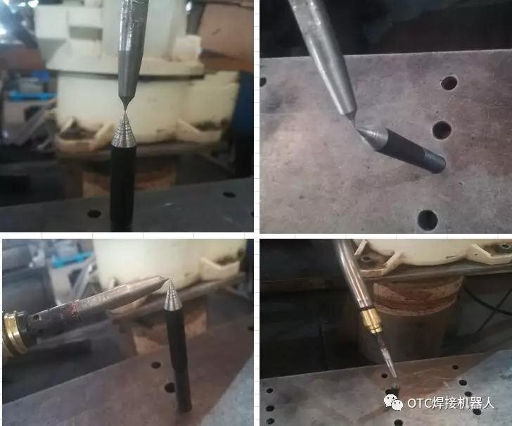
Outside the robot workbench, fabricate or prepare a highly rigid, sharp needle-like metal object as an external reference tip tool. Its tip position must remain absolutely stable throughout the entire calibration process without any visible displacement.
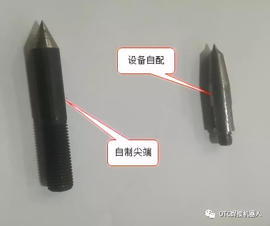
Vertically Fix the Tip Tool and Install the Torch Calibration Needle
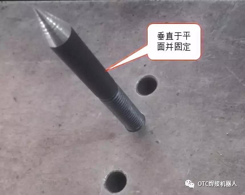
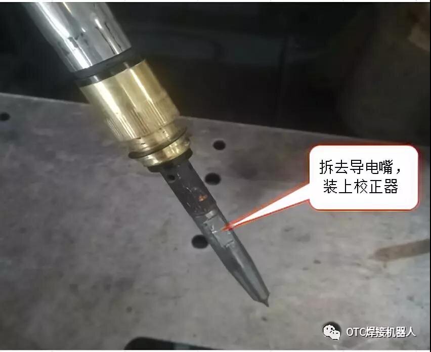
Securely and vertically lock the fabricated reference tip tool onto the workbench. Simultaneously, remove the protective nozzle at the front of the welding torch, and install the device’s dedicated calibration tip needle (or a rigidly straightened new welding wire) onto the contact tip holder of the welding torch as the moving calibration end.
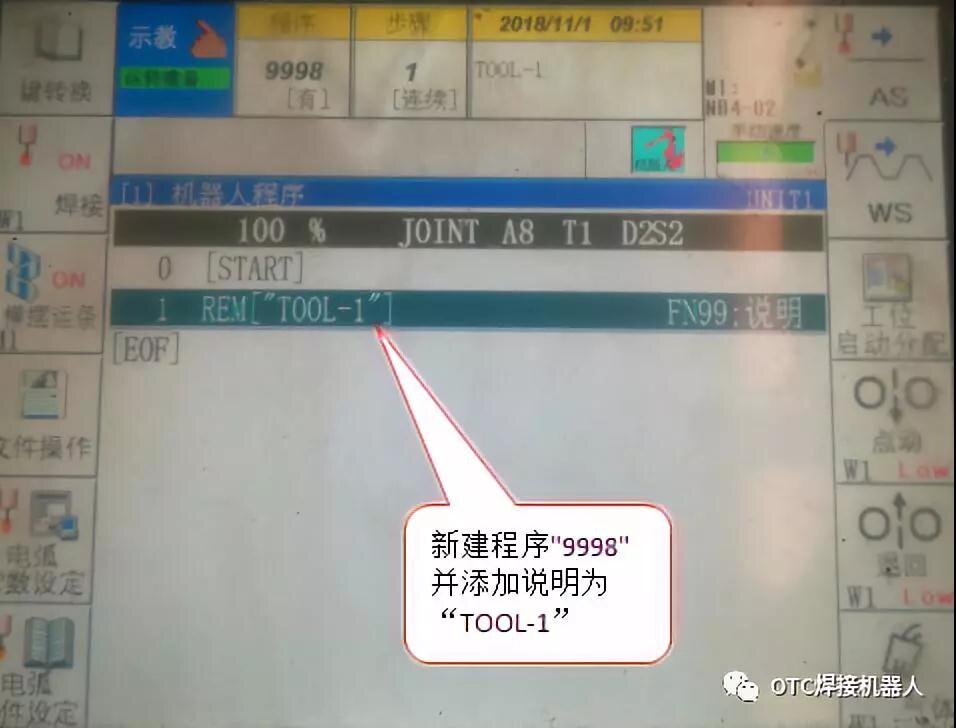
Change Level and Create Dedicated Calibration Program [9998]
Enter the teach pendant system and switch the protection level to the internal maintenance state. In the program management menu, create a dedicated temporary program for recording the tool coordinate system parameters. Designate the program number as [9998], and add an explanatory remark such as “TOOL-1”.
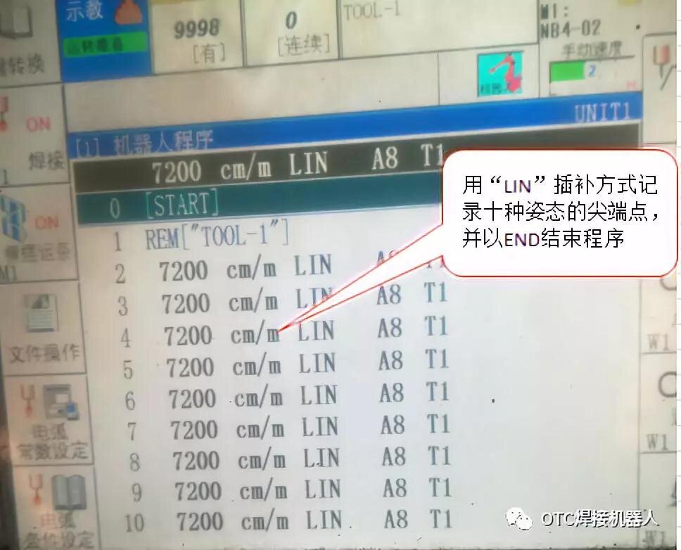
Accurately Record Ten Large-Angle Postures Using LIN Interpolation
Set the teach pendant’s motion interpolation method to [LIN] (Linear Interpolation). Manually manipulate the robotic arm to pose 10 different welding torch postures with the largest possible spatial amplitude, even approaching each joint’s limit. Core point: For each posture, you must ensure that the apex of the welding torch’s tip needle and the apex of the workbench’s reference tip tool achieve absolute “tip-to-tip” coincidence. Record a position point for each aligned posture, totaling 10 spatial position points, and add an END command at the end.
Enter the Underlying [Tool Setting] Console
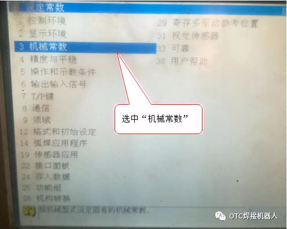
Ensure that the posture angle differences of the 10 spatial coordinate points recorded in program 9998 are large enough. Then, while pressing the rear safety enable switch (Deadman switch), press the front function key [Constant Setting]. In the pop-up system menu, select [Mechanical Constant], and further click to enter the [Tool Setting] branch.

Click [Simple Setting] in the Tool Parameter Window
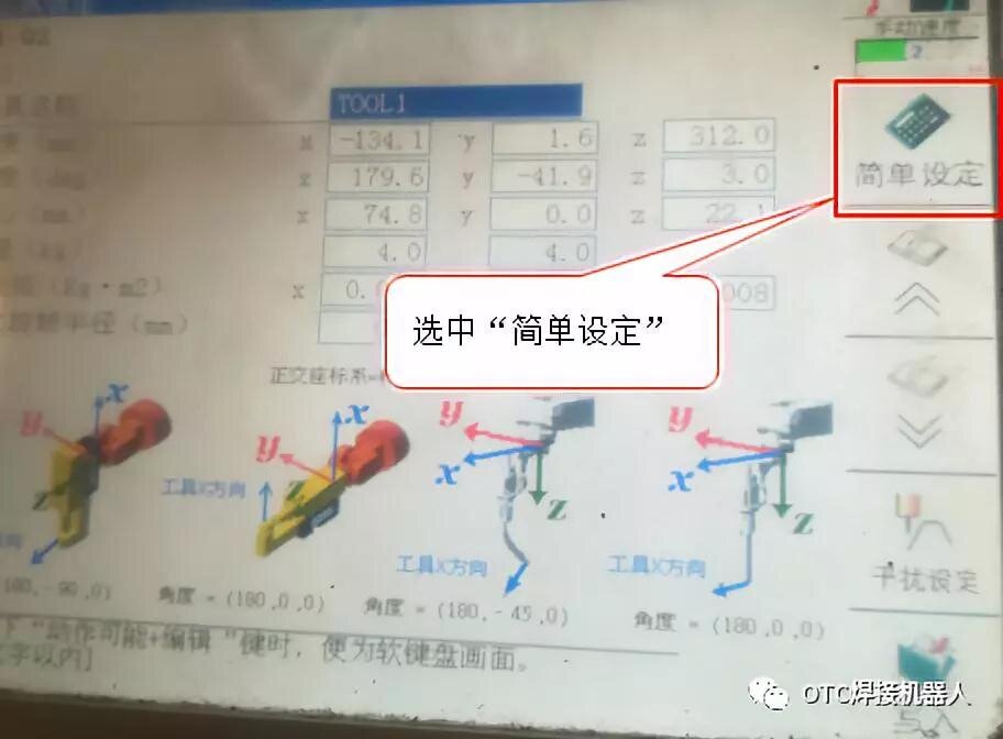
After successfully entering the underlying tool setting parameter window, below the detailed control bar for the corresponding tool number (e.g., Tool 1), click the [Simple Setting] soft key on the screen to activate the multi-point algorithm fitting calculation program.
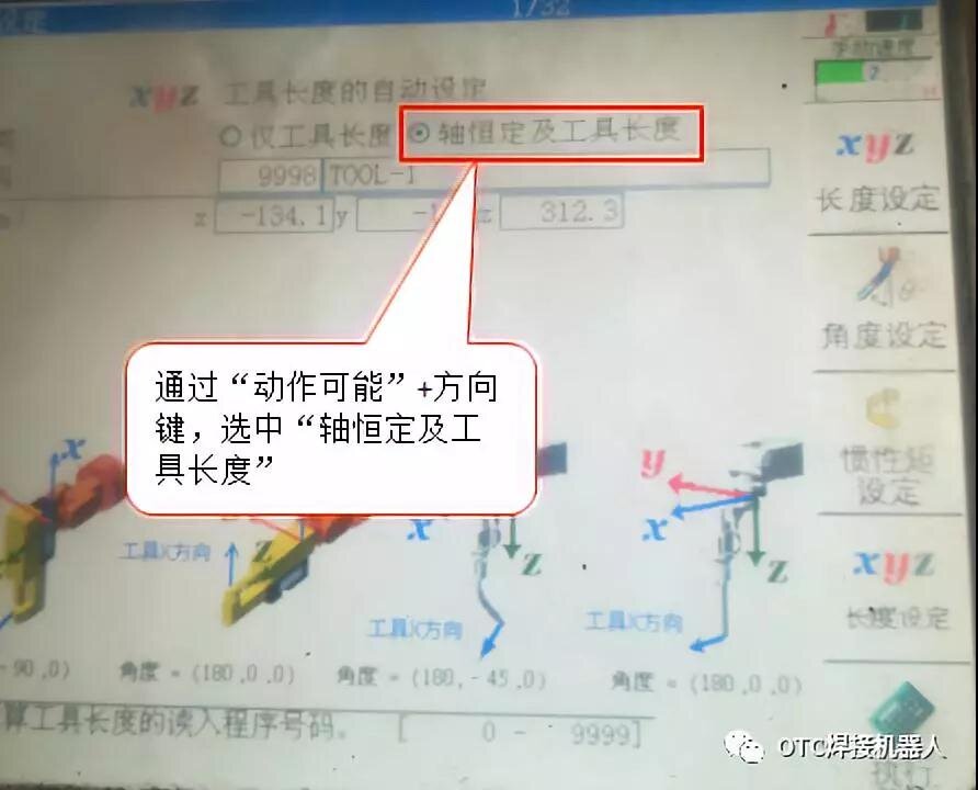
Select [Axis Constant and Tool Length] Calculation Mode
In the pop-up simple setting sub-menu, while holding the “Deadman” key, use the up and down arrow keys to move the cursor and select the [Axis Constant and Tool Length] parameter calculation option specifically designed for the standard ten-point method.
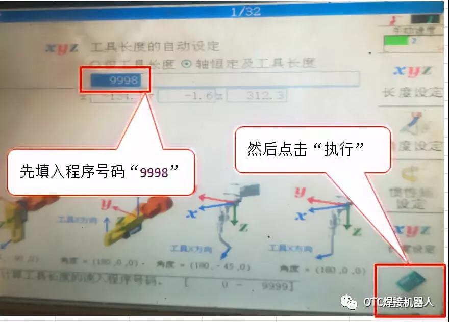
Correctly Input Program Number [9998] and Click Execute
Input the newly created calibration program number [9998] into the data source program guide box. After verifying its accuracy, click the [Execute] button at the bottom right of the screen. The system will automatically read these 10 spatial position postures and begin matrix calculation.
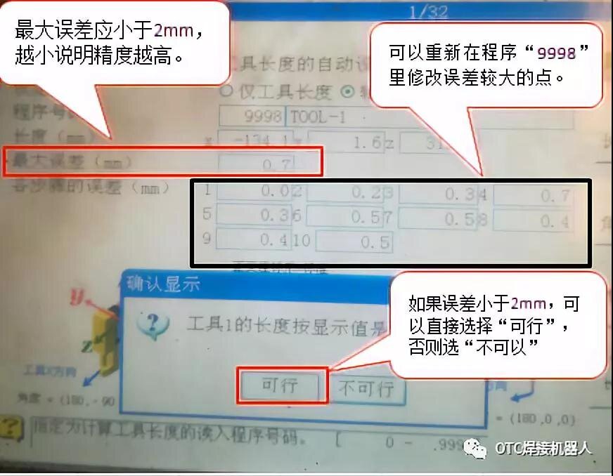
Strictly Verify the Calculation Error Result and Maximum Deviation Value
After the system matrix calculation is complete, a result value display box will pop up. Key point: You must strictly check the maximum error value. Standard requirements dictate that the maximum error should be less than 2mm (usually, high-precision arc welding stations require controlling it to around 0.5mm for optimal results). If the displayed result is less than 2mm, click [Possible]. If the error is greater than 2mm, it indicates that there is visual deviation in the tip-to-tip alignment of some points. You must exit the tool setting, correct the position points with large deviations in program 9998, and re-execute steps 5 to 9.
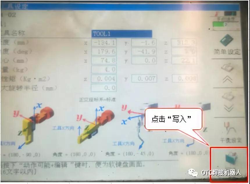
Click [Write] to Officially Save TCP Tool Coordinate System Data
Once the calculation result is approved, the system will present the final tool translation constants (X, Y, Z, and rotation angles around each axis). At this point, click the [Write] button at the bottom of the screen to forcibly save the tool constants. With this, the complete set of TCP precision calibration is officially successfully concluded.
⚠️ Core Error-Proofing and Pitfall Avoidance Guide for Precise TCP Calibration of Welding Torches on the Workshop Floor:
- Why must we insist on recording large-angle postures? Many beginners, when recording the 10 position points in step 4, pose overly single welding torch postures with minimal angle variations on each axis to save trouble. This leads to an insufficient slope sample for the system during matrix fitting, and the calculated tool center point constants will produce severe geometric distortion. Please be sure to let the robot make large-range pitching and flipping within the limit range of the J4, J5, and J6 axes around the reference tip.
- How to eliminate the error interference of welding wire stick-out length? In actual arc welding, the TCP is entirely based on the tip of the welding wire protruding from the front end of the contact tip. Because the welding wire is flexible, it is prone to slight bending. It is recommended that after completing step 10 to write, install the standard protective nozzle back, and in manual teaching mode, switch the coordinate system to the [Tool Coordinate System]. Try manually rotating the robot’s various axis postures and strictly visually observe whether the welding wire tip rotates in place in space without any drifting. If the welding wire tip moves in circles, it means the calibration failed, and you must replace it with a brand new straight contact tip and recalibrate.
️ Fast Access to Robot Welding Torch Calibration Wear Parts and Original Technical Support
Frequent TCP coordinate system drift and a maximum calculation error that cannot fall below 2mm are usually caused by carbonization and loosening of the internal insulator of the welding torch, variations in the stiffness of the front wire feeder mounting bracket, or long-term severe collisions that cause serious mechanical backlash in the RV/harmonic reducers of the robotic arm joints. Welcome to contact us for the latest official standard quotes and technical alternative solutions for original high-rigidity torch brackets, quick-change air-cooled/water-cooled welding torch assemblies, and advanced anti-collision sensor accessories:
How to Use Original High-End Electromechanical Accessories to Improve the TCP Stability of Automatic Arc Welding Stations?
In highly automated multi-station assembly lines, even the slightest drift of the welding torch tool center point means an extremely high geometric rejection rate. In order to thoroughly guarantee the rigorous reproducibility of the process trajectory, we strongly recommend that the equipment departments of all enterprises achieve two points: First, put an end to the use of non-original high-imitation low-stiffness torch brackets and aftermarket connecting bolts, to prevent biomechanical fatigue deformation caused by inertial stress during frequent high-speed positioning; Second, persist in equipping the automatic torch cleaning and wire cutting workstations (such as standard torch cleaners) with high-hardness quenched reamers (such as 5096-306) and high-elasticity limit micro-switches to ensure that every mechanical slag cleaning will not exert abnormal mechanical impact on the welding torch swan neck (such as L10613B00). We promise that the full range of OTC original high-precision welding torch body assemblies, high-stiffness insulating flanges, and safety anti-collision sensor systems we supply are 100% brand new, authentic products from official channels. If you need to understand today’s real-time inventory quotes for accessories, obtain a full set of external wiring diagrams for the control cabinet terminal block, or Fronius special high-precision welding accessory information, please feel free to consult our technical service team at any time.